Try the CHERIoT platform on the Arty A7 100T FPGA
When we started prototyping CHERIoT hardware, we used an MPS3 FPGA board from Arm. This is a much more powerful than you need to simulate a small embedded core and, at over $5,000, is out of the price range of any hobbyist who manages to keep their level of obsession down to healthy levels.
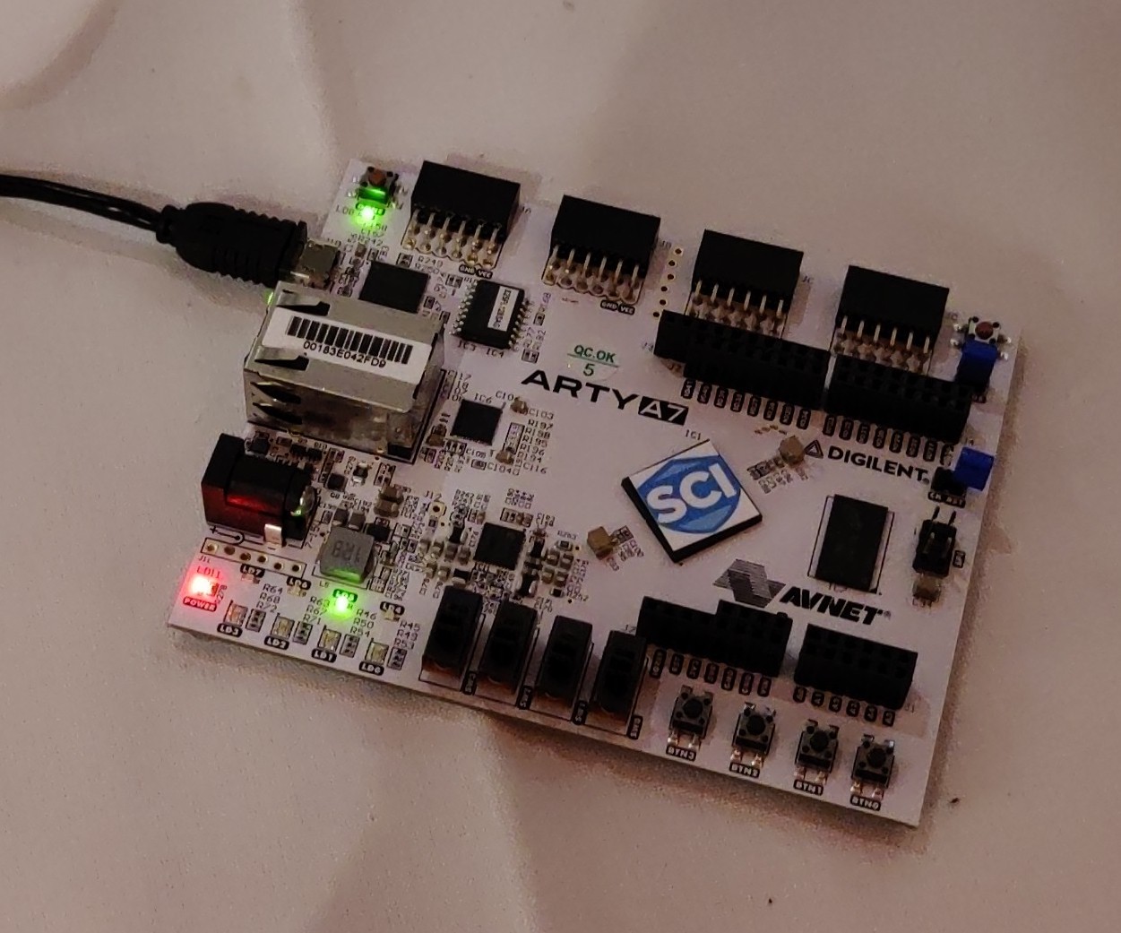
The CHERIoT small and fast FPGA emulator (SAFE) configuration is a simple integration of the CHERIoT Ibex on the Arty A7 100T FPGA. The A7 is a relatively cheap ($299) FPGA development board that is popular in the RISC-V hobbyist community and has a price that is a lot more attractive for hobbyist use.
The SAFE configuration is intended for early prototyping, it is not quite yet representative of a full CHERIoT SoC, but it has the key components:
- A core that implements the CHERIoT ISA.
- 256 KiB of Memory that carries tags and supports the load filter for revocation.
- An asynchronous hardware revoker.
It also provides a UART and some GPIO pins for LEDs, buttons, and switches. The board provides an Ethernet PHY but sadly not a MAC. Hopefully a future version will add a soft MAC and then we’ll have a network connection and be able to prototype IoT things on this board.
If you have an A7, clone the CHERIoT SAFE repository and look in the build directory.
This has a script build_arty_a7 that builds a bitfile for the A7.
Currently, this builds without support for the switches and buttons.
That will hopefully change soon, but if it hasn’t yet then edit build_arty_a7 and replace arty-cheri-a7-100.xdc with arty-cheri-a7-100-buttons.xdc.
If there is no arty-cheri-a7-100-buttons.xdc file, then it’s probably replaced the old one.
The SAFE configuration doesn’t yet provide tools to load firmware over JTAG (coming soon!) and so, in the interim, we’ve written a small bootloader that lives in ROM and can load a hex file over the UART. The hex file for this is baked into ROM during build.
This loader resets all of the memory to a pristine state between runs and starts the firmware once it’s booted. Its output on the UART will be in red, so that it’s easy to differentiate from normal output from the firmware.
This isn’t the fastest thing in the world. It loads at 115,200 bits per second, but the hex file is nine bytes per 32-bit word (eight digits and a newline) and so it takes about 20 seconds to load a firmware image. This is much faster than the ten minutes that it takes a fast machine to build a new bitfile with an updated version of the hex file baked in.
The build_arty_a7 script in the build directory builds a firmware image including that you can then load onto the device.
This script requires a working Vivado installation, but hopefully if you have an Arty A7 then you’ve suffered through the pain of the Vivado installer already
Installing Vivado was (by a large margin) the hardest and most time consuming part of the entire process of doing CHERIoT RTOS bringup on the A7.
LED 4 is connected to the core’s heartbeat. If it’s flashing then the CHERIoT Ibex is running correctly. LEDs 5 and 6 are available for software to use.
Once you’ve loaded this image to the FPGA, you can connect your favourite serial terminal program and send it files:
I’m using minicom here (started with -c on to get colour output).
It is set to run at 115,200 Baud, 8 data bits, 1 stop bit, no parity.
I can send files down the connection with the ‘paste file’ option in the menu.
My copy of minicom seems to have a bug where pasting large files stalls after a little while and you have to hit a key for it to resume. This is why the bootloader prints a dot for every 1 KiB of code it’s received: so that you can spot it stalling and prod the serial console.
The firmware shown above is a completed version of the compartmentalisation exercise, which loads JavaScript bytecode (compiled with microvium) via the UART and runs it. I haven’t put this online yet, because I don’t want to take away the fun of doing the compartmentalisation exercise for yourself.
The first loaded JavaScript tries to leak the secret (it can’t!), the second shows a crash in the compartment (which crashes the entire system in the non-compartmentalised version). The final one is quite boring in the screen recording but flashes the two LEDs at a rate controlled by the switches. I now have the worlds most secure flashing LED! And, really, if you’re flashing an LED without using a JavaScript interpreter on a privilege-separated RTOS then you’re just not trying hard enough.
The code to build for the Arty A7 configuration is merged, simply set the board to ibex-arty-a7-100 and it will work.
You can try the examples in the RTOS repository like this (--board=ibex-arty-a7-100 in the xmake config step), or build something of your own.
If you #include <platform-gpio.hh> then you get a definition for GPIO pins connected to the LEDs, switches, and buttons that you can use, look in the header for the APIs.
Note that this is a very rough interface and will probably change later.